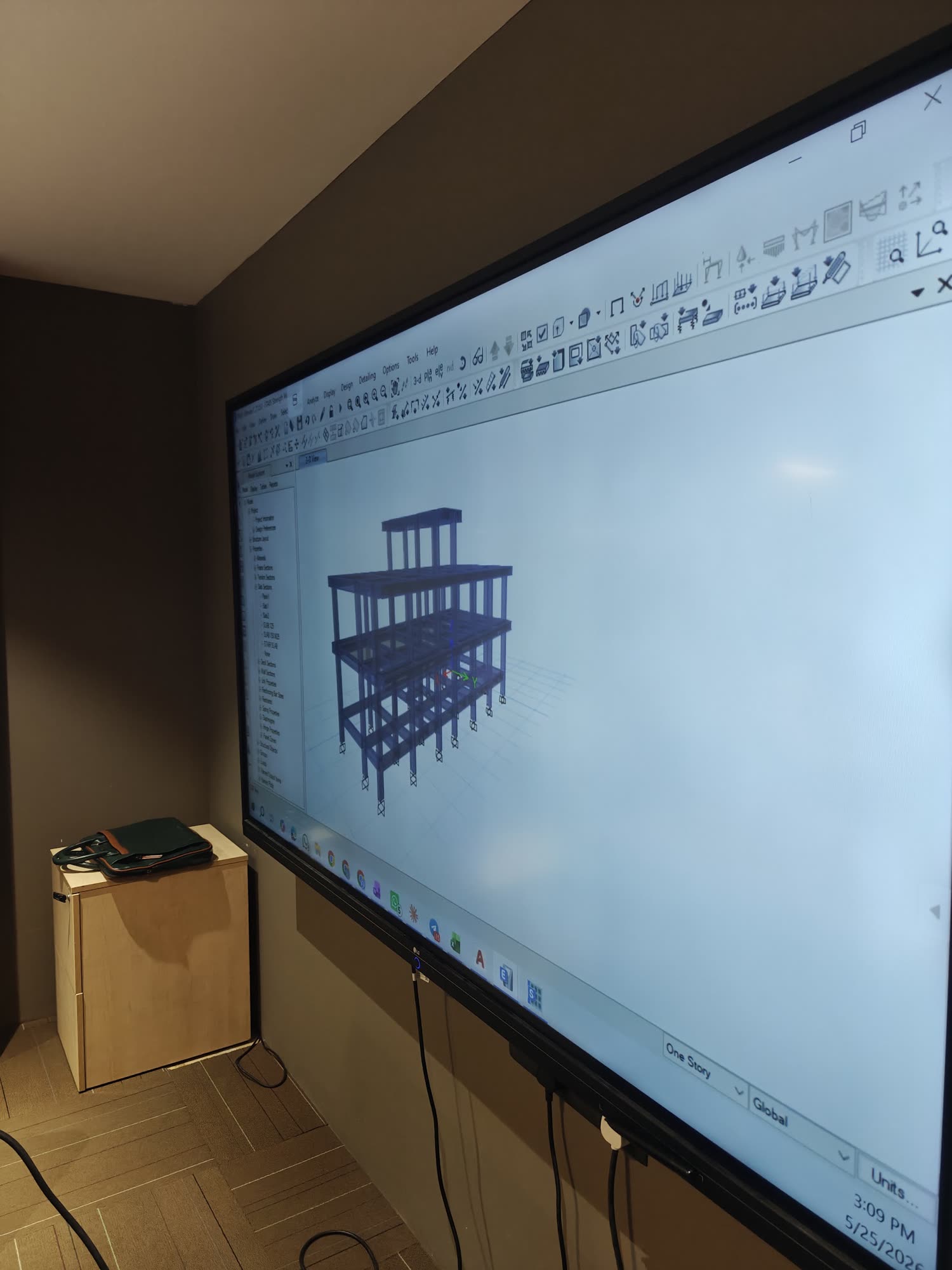
Most people see the result of structural design — a set of drawings on site — but not the process behind it. Here is the workflow we follow at StruxLabs for an RCC building, and the same one we teach in the Civil Engineering Launchpad.
1. Start with approved architectural drawings
Everything begins with the architect’s floor plans, elevations and sections, usually as approved by the Panchayat, Municipality or Corporation. Before modelling anything, we check for red flags: columns that don’t stack between floors, unusually long spans, floating columns and missing levels.
2. Clean up and plan the structure in AutoCAD
The architectural file is cleaned up — unnecessary layers removed, grid lines set — and column positions and centrelines are planned. This is where structural sense matters most: column placement, load paths and span checks decide how efficient the whole building will be.
3. Model, analyse and design in ETABS
The centreline drawing is imported into ETABS. We define materials, sections, slabs, storeys and supports, then apply loads:
After analysis we check deflections and storey drifts, then design beams, columns and slabs.
4. Design the foundation in SAFE
Column reactions from ETABS go into SAFE together with the safe bearing capacity (SBC) from the soil investigation report. Isolated, combined and raft footings are sized and reinforced there; where the soil calls for piles, they are designed to IS 2911 from the pile capacities in the soil report[6].
5. Produce GFC drawings
Member sizes and reinforcement are drafted into Good-For-Construction drawings: column layouts, footing details, beam and slab reinforcement, staircase details and general notes. These are what the contractor builds from, detailed to the practice in SP 34[7].
6. Review and site support
Drawings are checked before issue, and site queries are answered during construction. A design is only finished when it is built correctly.
Sources
- [1]IS 875 (Part 1):1987 — Design Loads: Dead Loads (BIS)
- [2]IS 875 (Part 2):1987 — Design Loads: Imposed Loads (BIS)
- [3]IS 1893 (Part 1):2016 — Criteria for Earthquake Resistant Design of Structures (BIS)
- [4]IS 875 (Part 3):2015 — Design Loads: Wind Loads (BIS)
- [5]IS 456:2000 — Plain and Reinforced Concrete, Code of Practice (Bureau of Indian Standards)
- [6]IS 2911 (Part 1/Sec 2):2010 — Design and Construction of Pile Foundations (BIS)
- [7]SP 34:1987 — Handbook on Concrete Reinforcement and Detailing (BIS)
Indian Standards are published by the Bureau of Indian Standards; links point to public copies. Always design to the current edition.
This article is general information, not engineering advice for your building. Always have a qualified structural engineer check your structure. Read our disclaimer.
Learn this hands-on, or let us do it for you.