The project
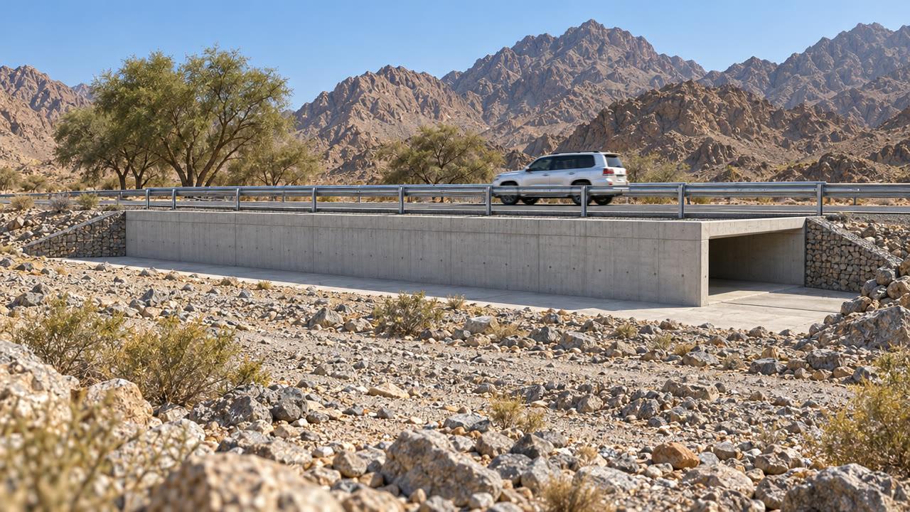
A reinforced concrete box culvert with retaining walls for a development in Oman, designed to the master developer's guidelines.
The challenge
A box culvert carries the soil above it and the traffic loads on top, while its walls hold back the ground on both sides. The design also had to follow the master developer's own guidelines for culverts and utilities.
Our approach
- Followed the developer's box-culvert and utilities guidelines
- Designed the box section (400 mm members) and retaining walls from the soil investigation
- Element design with calculation sheets
How a box culvert is designed
A box culvert is checked as a closed concrete frame. The top slab carries the fill and the traffic, the walls resist soil pressure pushing in from both sides, and the base slab spreads everything into the ground. Each of these load cases is combined to find the worst bending and shear in every element, and the retaining walls are checked separately for overturning and sliding using the soil properties from the investigation.
Outcome
Box culvert and retaining wall design with drawings.
The structure in numbers
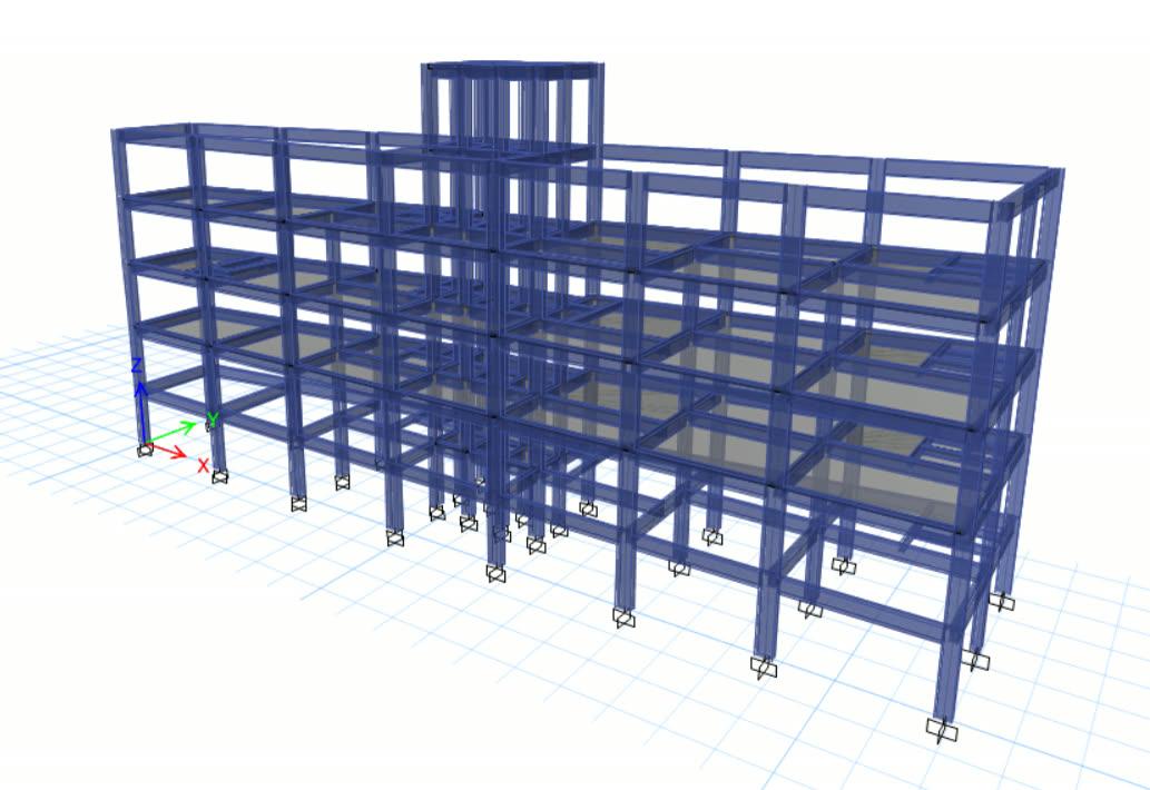
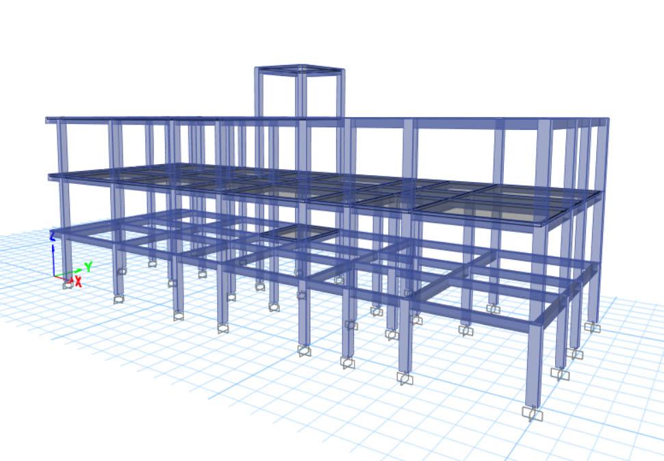
The ETABS model of this structure has 1 level and rises 1.3 m over a footprint of about 22 × 8 m. A modal analysis was run to check how the building sways and vibrates before the members were finalised.
Structural system
- Slabs
- 400 mm thick
- Walls (modelled)
- 250 mm thick
- Analysis
- 3D ETABS model — linear static analysis